Materials
Silica (latin : Silex) : oxide of silicon, exist in nature as quartz
Fluoride glass : non oxide class, fluoride of various metal
Phosphates glass : a class of optical glasses composed metaphosphates of various metal
Chalcogenide glass : [sulfur, selenium, tellurium], react with more electropositive elements
Guiding light by refraction, first discover:
Daniel Colladon (Swiss) and Jacques Babinet (French) in Paris, in 1840, 12 years later by JohnTyndall (Irish) in London.
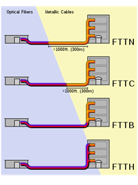
FTTN / FTTLA (fiber-to-the-node, -neighborhood, or -last-amplifier)
FTTC / FTTK (fiber-to-the-curb/kerb, -closet, or –cabinet)
FTTB (fiber-to-the-building, -business, or –basement)
FTTH (fiber-to-the-home)
Optical Fiber: flexible and transparent fiber made by drawing glass (silica) or plastic.
-Advantage: transmission over longer distances and higher bandwidth that wire cables.
-Nature of transmission: the light
Fiber is immune to electromagnetic interference.
- MMF: Many propagation paths or transverse mode are called multi-mode fibers (MMF). This mode have a wider core diameter, and used for short distance where high power must be transmitted. The MMF cable is orange and aqua.
Diameter: 50/125 µm OM3
Less expensive than SMF
Speed:
0—550 m: 10Gbit/s
0—1000 m: 1Gbit/s
0—2000m: 100Mbit/s (100base-FX)
Classification determined by the ISO 11801:
OM1: 62.5/125 µm
OM2: 50/125 µm
OM3: 50/125 µm (laser optimization)
OM4: 50/125 µm
- SMF: Single mode is called SMF. This mode is used for most communication links longer than 1,000 meters.
Diameter: 50/125 µm OM2
Color MMF cable is yellow.
Structure:
1. Core: 8µm diameter
2. Cladding: 125 µm diameter
3. Buffer: 250 µm diameter
4. Jacket: 400 µm diameter
Speed records
|
Year |
Corp. |
Effect. Speed Tbit/s |
WDM channel |
Per channel speed Gbit/s |
Distance in KM |
|
2009 |
Alcatel-Lucent |
15 |
155 |
100 |
90 |
|
2010 |
NTT |
69.1 |
432 |
171 |
240 |
|
2011 |
KIT |
26 |
1 |
26 Tbit/s |
50 |
|
2011 |
NEC |
101 |
370 |
273 |
165 |
|
2012 |
NEC, Corning |
1.05 Pbit/s |
12 core fiber |
|
52.4 |
KIT : Karlsruhe Institute of Technology
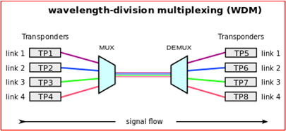
DWDM : terminal multiplexer
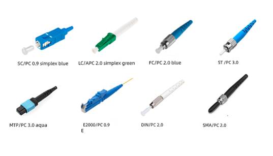
Types of connector:
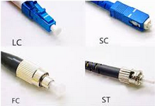
SC 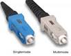
: Developed by Nippon Telegraph and Telephone (NTT),
In mid-eighties. Suited for datacom and telecom application
Including point-to-point and passive optical network.
LC
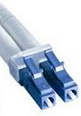
: Successor of SC, inventor: Lucent Corp. It have a latch,
as opposed to the SC locked tab. It continue to grow in
FTTH arena.
FC

: Fist to use a ceramic ferrule, type of connection is insertion,
Quicker to connect, less expensive.
However, the screw-on collet of the FC does make it
particularly effective in high vibration environments.
ST
 :
Developed by AT&T shortly after FC, it uses a bayonet fitment
:
Developed by AT&T shortly after FC, it uses a bayonet fitment
Rather than a screw thread. Usage is declined in 2010es for
the same reason as the FC.
It cannot be terminated with an angled polish,
which limits use in single mode fiber and FTTH applications.
It is most common in network environments such as campuses,
corporate networks and in military applications where the quick
connecting bayonet had its advantages at the time. High cost.
MPO/MTP
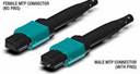
: Invented by NTT around 1980, become popular in 2010
under branded version : Multiple Fiber Push-On/Push-Off,
Male/Female connector.
It can support up to 24 fibers in a single ferrule.
In high density patch environments such as datacenters
they are used extensively, both at single mode and
multi-mode wavelengths.
The attenuation loss can be higher than a single ceramic
ferrule connector.
---------------------------------------------- 2nd part : Fiber Connector Web -----------------------------------------
Fiber Connectors - what's the difference?
Source : http://www.ppc-online.com/blog/fiber-connectors-whats-the-difference
: Shaun Trezise
---------------------------------------------------------------------------------.
Given the variety of splice options available to fiber network planners today
identifying the best connector for FTTH can be overwhelming. Consequently often
not much thought is given to connector selection with choice driven by cost,
availability or what’s been used before. However each connector has its own
unique design and therefore, pros and cons. Over time or depending on project
size this can have a dramatic impact on deployment speeds and costs.
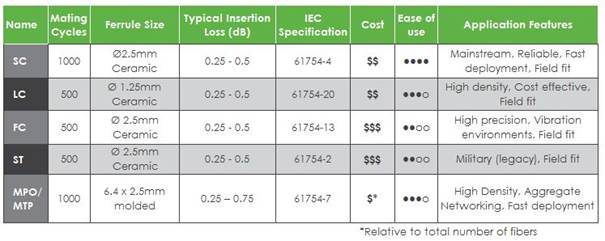
So what are the differences and what do they mean to your implementation? This
table of common connectors gives an overview of strengths and weaknesses, with
more detail in the accompanying descriptions:
1. SC Connector
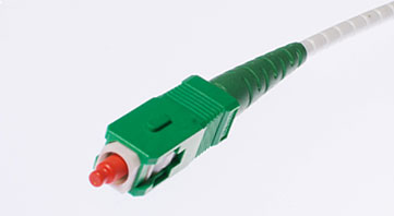 The SC was developed by the laboratories at Nippon Telegraph and Telephone (NTT) in the mid-eighties,
and was one of the first connectors to hit the market following the advent of
ceramic ferrules. Sometimes referred to as the ‘square connector’ the SC has a
push-pull coupling end face with a spring loaded ceramic ferrule. Initially
intended for Gigabit Ethernet networking, it was standardized into the
telecommunications specification TIA-568-A in 1991 and slowly grew in
popularity as manufacturing costs came down. Due to its excellent performance
it dominated fiber optics for over a decade with only the ST rivalling it.
Thirty years on, it remains the second most common connector for polarization
maintaining applications. The SC is ideally suited for datacoms and telecoms
applications including point to point and passive optical networking.
The SC was developed by the laboratories at Nippon Telegraph and Telephone (NTT) in the mid-eighties,
and was one of the first connectors to hit the market following the advent of
ceramic ferrules. Sometimes referred to as the ‘square connector’ the SC has a
push-pull coupling end face with a spring loaded ceramic ferrule. Initially
intended for Gigabit Ethernet networking, it was standardized into the
telecommunications specification TIA-568-A in 1991 and slowly grew in
popularity as manufacturing costs came down. Due to its excellent performance
it dominated fiber optics for over a decade with only the ST rivalling it.
Thirty years on, it remains the second most common connector for polarization
maintaining applications. The SC is ideally suited for datacoms and telecoms
applications including point to point and passive optical networking.
2. LC Connector
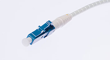 Considered by some to be the modern replacement of the SC connector;
its introduction was less successful, in part due to initially high license
fees from inventor Lucent Corporation. Also a push-pull connector, the LC
utilizes a latch as opposed to the SC locking tab and with a smaller ferrule it
is known as a small form factor connector. Having half the footprint of the SC
connector gives it huge popularity in datacoms and other high-density patch
applications, as its combination of small size and latch feature make it ideal
for densely populated racks/panels. With the introduction of LC compatible
transceivers and active networking components, its steady growth in the FTTH
arena is likely to continue.
Considered by some to be the modern replacement of the SC connector;
its introduction was less successful, in part due to initially high license
fees from inventor Lucent Corporation. Also a push-pull connector, the LC
utilizes a latch as opposed to the SC locking tab and with a smaller ferrule it
is known as a small form factor connector. Having half the footprint of the SC
connector gives it huge popularity in datacoms and other high-density patch
applications, as its combination of small size and latch feature make it ideal
for densely populated racks/panels. With the introduction of LC compatible
transceivers and active networking components, its steady growth in the FTTH
arena is likely to continue.
3. FC Connector
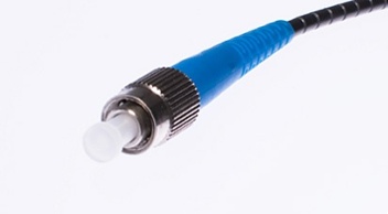 The FC was the first optical fiber connector to use a ceramic
ferrule, but unlike the plastic bodied SC and LC, it utilizes a round
screw-type fitment made from nickel-plated or stainless steel. The connector
end face relies on an alignment key for correct insertion and is then tightened
into the adaptor/jack using a threaded collet. Despite the additional
complexity both in manufacturing and installation, it’s still the connector of
choice for precise measuring equipment such as OTDRs.
The FC was the first optical fiber connector to use a ceramic
ferrule, but unlike the plastic bodied SC and LC, it utilizes a round
screw-type fitment made from nickel-plated or stainless steel. The connector
end face relies on an alignment key for correct insertion and is then tightened
into the adaptor/jack using a threaded collet. Despite the additional
complexity both in manufacturing and installation, it’s still the connector of
choice for precise measuring equipment such as OTDRs.
Initially intended for datacoms and telecoms applications, its use has reduced since the introduction of the SC and LC. These deliver similar performance to the FC but both have less expensive components and are quicker to connect. However, the screw-on collet of the FC does make it particularly effective in high vibration environments, ensuring that the spring-loaded ferrule is firmly mated.
4. ST Connector
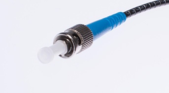 The ST connect was developed by AT&T shortly after the arrival
of the FC. At a glance they can be mistaken for one another but the ST uses a
bayonet fitment rather than a screw thread. Usage has declined in recent
decades, for the same reasons as the FC. Additionally it cannot be terminated
with an angled polish, which limits use in single mode fiber and FTTH applications.
The ST connect was developed by AT&T shortly after the arrival
of the FC. At a glance they can be mistaken for one another but the ST uses a
bayonet fitment rather than a screw thread. Usage has declined in recent
decades, for the same reasons as the FC. Additionally it cannot be terminated
with an angled polish, which limits use in single mode fiber and FTTH applications.
Deployed predominately in multi-mode datacoms it is most common in network environments such as campuses, corporate networks and in military applications where the quick connecting bayonet had its advantages at the time. It is typically installed into infrastructures that were built at the turn of the century; when retro-fitting, STs are typically swapped out for more cost effective SC and LC connectors.
5. MTP/MPO connector
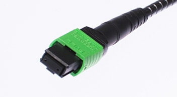 The MT ferrule connector is another of NTT’s inventions and has been
around since the 1980s, although the technology has only recently become
popular under branded versions of the Multiple Fiber Push-On/Pull-Off
connector, such as MTP and MPO. It is larger than the other connectors but for
good reason - it can support up to 24 fibers in a single ferrule.
The MT ferrule connector is another of NTT’s inventions and has been
around since the 1980s, although the technology has only recently become
popular under branded versions of the Multiple Fiber Push-On/Pull-Off
connector, such as MTP and MPO. It is larger than the other connectors but for
good reason - it can support up to 24 fibers in a single ferrule.
Multi-fiber connectors are not currently designed for field-fit applications so must be lab terminated. In high density patch environments such as datacenters they are used extensively, both at single mode and multi-mode wavelengths. On a ‘per-fiber’ basis the costs are relatively inexpensive. However as might be expected, the attenuation loss can be higher than a single ceramic ferrule connector. That being said, it is possible to order ‘low loss’ MTP/MPO connectors which have comparable insertion loss performances. These are more costly however.
Network planners should also consider that whilst still using a uniter/adaptor much like other connectors, the MTP/MPO must also be mated to an opposing male or female connector. This may require more than one connector specification or type within inventory, adding to cost and complexity.
Because the sequence of the fibers cannot physically be changed after termination, the connector is often supplied with a fan-out assembly at the opposing end (such as LC, SC FC etc.). This allows the operator to change channels simply by re-patching the fanned-out side of the cable. The consequence of this is that the small form high density design of the MTP/MPO will only benefit one side of the assembly.
More common in datacoms, these connectors are starting to appear in FTTH applications. They should therefore be considered if drivers include quick deployment of aggregate fibers, high density patching or where smaller ODFs and nodes might be crucial.
The differences between types of connectors can easily overlooked in the complex planning around fiber deployments. However taking the time to select the right one for the job can deliver big benefits when it comes to speed and cost, so take the time to investigate your options before making your connector choice.
----- End of document -----
----- eof -----